Define yard path connection properties
Use the Add Yard Path Connection form to define the properties of a single yard path connection. Creating this connection requires you to specify ingress and egress vertices, traffic flow, and access constraints.
There is also a Add Yard Path Connections (on page 1) (plural) form, which enables you to create all row vertices and row paths at once.
To define yard path connection properties:
-
In the Label field, enter a name for the yard path connection.
-
From the Ingress Vertex and Egress Vertex lists, select the vertex for accessing and exiting the yard path, respectively.
-
Select the Ingress At Low End check box if the entrance should be at the low end.
This check box is used by XPS only. XPS uses this information to determine block exit distances. You should set the value in accordance with the location of the ingress vertex. For example, if the ingress vertex for the yard bin path for block A is vertex 1, and vertex 1 is closest to logical row 1, then you should select this check box.
XPS does not have a spatial model; if you set this value incorrectly, then XPS assumes that the vertex location is on the opposite side of the block.
-
From the Traffic Flow list, select a value to specify traffic flow as either ascending, descending, or both.
By default, the traffic flow is unknown.
-
Select any of the following check boxes to specify access constraints:
-
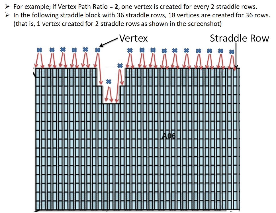
In the Vertex Path Ratio field, enter the number of straddle rows to be considered for creating one vertex. Values should be between 1 to 10 (inclusive).
For example, if you enter the value '2' (means, 2 straddle rows), one vertex will be dynamically created for every two straddle rows. So, in a straddle block with 36 rows, a total of 18 vertices will be dynamically created as shown below:
-
Click Save.
 Yard Models